- Published on
Thermomo-jacket
- Authors

- Name
- Justin James Clayden
Thermomo-jacket

The 'Thermomo-jacket' is a wearable thermometer that represents the temperature inside the jacket as different hues of colour. It demonstrates Justy's ability to combine embedded electronics, microcontroller programming, and physical prototyping into a single functioning garment. At around 10 degrees Celsius the LED lights blue. Justy took a quick walk in the winter air before taking this photo to get the reading down. Brrrr!

Things are heating up -- this is around 18 degrees. Temperature is mapped to hue. The saturation and brightness of the colour was kept at 100%.

In the mid 20's the LED glows yellow then orange. This is a really warm jacket, so a fast temperature rise is inevitable.

In the high 20's the LED glows red, or even a little violet. Hot stuff... coming through!

The LED is very bright, and the three colours are produced by three separate LEDs, so a diffusing material is needed to cover it. Otherwise, a colour split occurs. In the picture above, the colour should be orange, but separate green and red colours are visible. For the series of pictures above that, a small piece of masking tape was used. Obviously that won't do for high fashion!

Here's the LED itself -- its pins have pushed through the jacket, and are wired up on the other side. It's an RGB LED, which means the individual red, green, and blue lights can be controlled independently.
The LED and the thermistor (a resistor that changes its resistance with temperature) are connected to the microcontroller board:

A: In the foreground is a power regulator, which provides stable power to the microcontroller. B: This is the microcontroller. C: The brown pillowy thing in the background is the ceramic oscillator -- the component that provides a 16MHz timing signal to the microcontroller.
Here is how the thermistor was wired up:

The Arduino board has several analogue inputs that require a varying voltage. This voltage needs to change as a function of the resistance of the thermistor. The classic approach is a voltage divider:
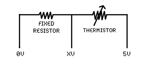
As the resistance of the thermistor changes, so does the voltage 'XV'. This value is read by the Arduino board, and then in software the reading is mapped to colour. The thermistor is hidden near the LED, next to the wool of the jacket, and so it tends to get very warm very quickly.
Here's another detail of the wiring to the thermistor:

The blue wire gives the variable voltage level. Notice how everything is heat-shrunk. This ensures no short circuits can occur as the thermistor moves around inside the jacket.
Future plans include adding a second thermistor on the outside of the jacket, enabling measurement of the difference between inside and outside temperatures and representing that delta via the LED.